The universal board SB 4.0 is designed for receiving and processing data from multiple sensors, for further decision-making and execution of the preset algorithms. An interface is designed in OS Windows. It vividly displays the telemetric readings from the sensors and power supply, the state of the buttons and servos and allows sending commands to the microcontroller.
The technology used in the board SB 4.0 is an open – source hardware/software platform, which in combination with the sensors, periphery and your needs allows creating new products and solutions for the Internet of Things (IoT).
The SB 4.0 board is ideal for the academic curricular of schools, universities, and STEM centers. Using this board with additional electronics and periphery, it is possible to independently develop one’s own project.
The board is an ideal solution students of high schools, colleges, and universities, for makers, individual and corporative vendors.
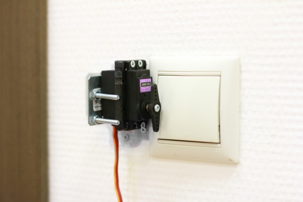
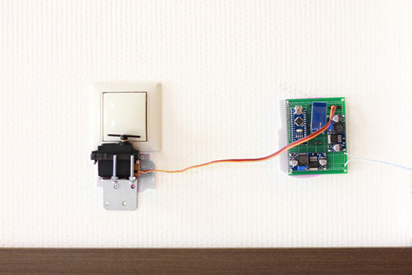
One of the potential variants of its application is development of a “smart home” DIY system.
A C-like language is used for programming. Developing is carried out in the Arduino IDE environment.
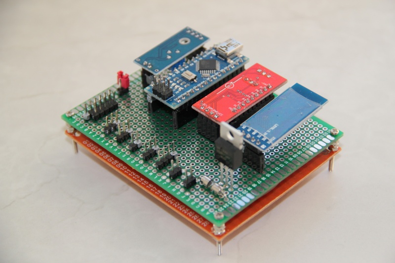
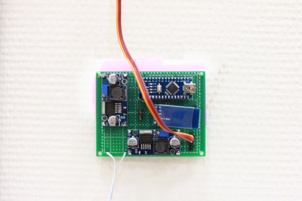
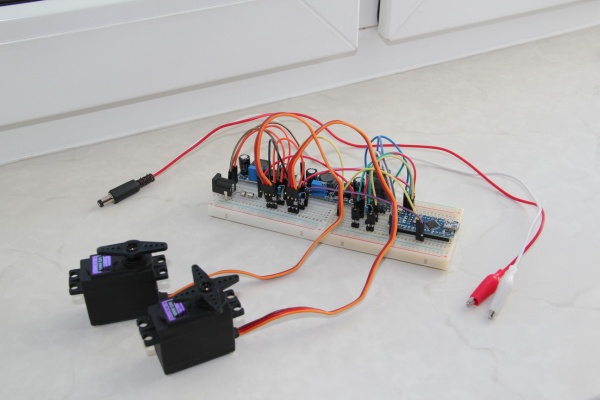
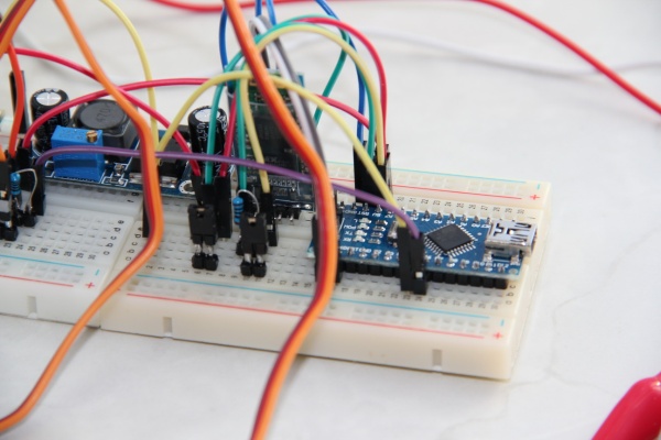
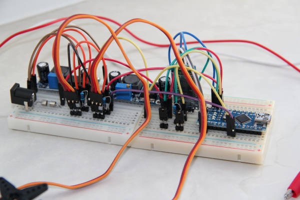
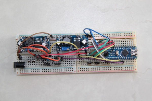
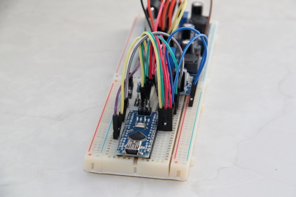
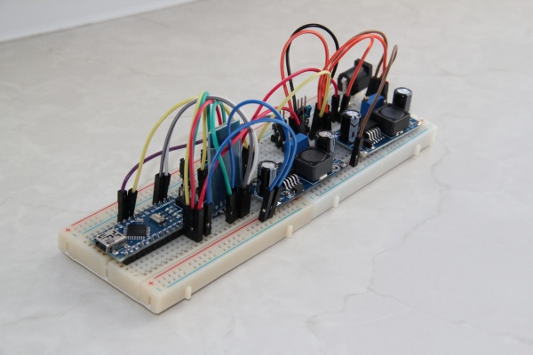
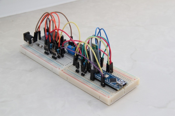
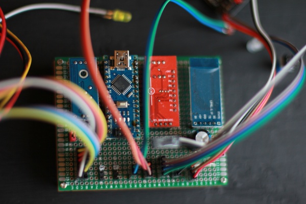
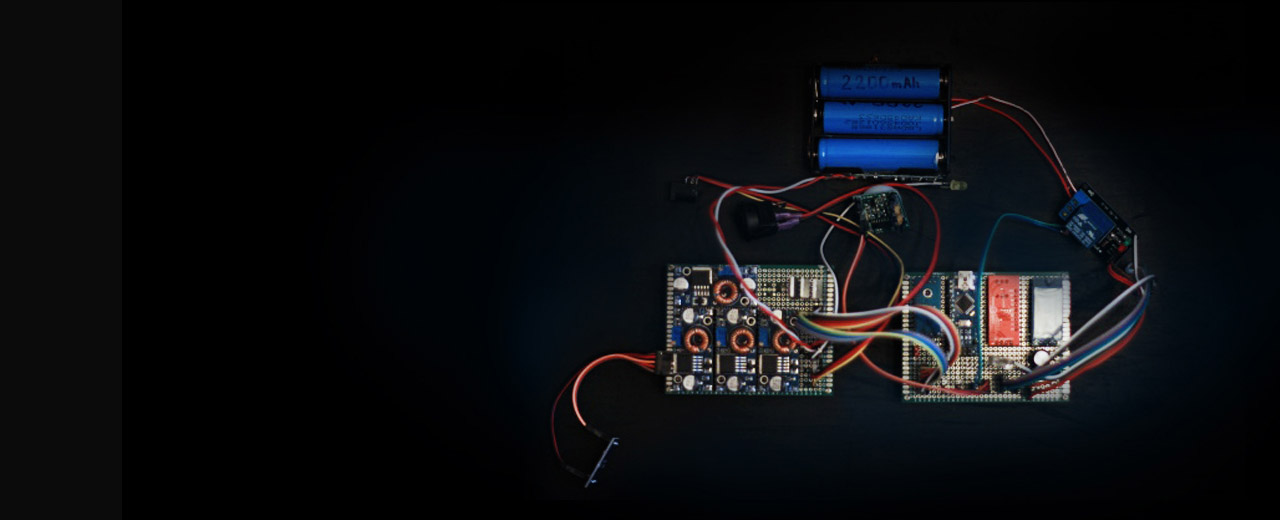
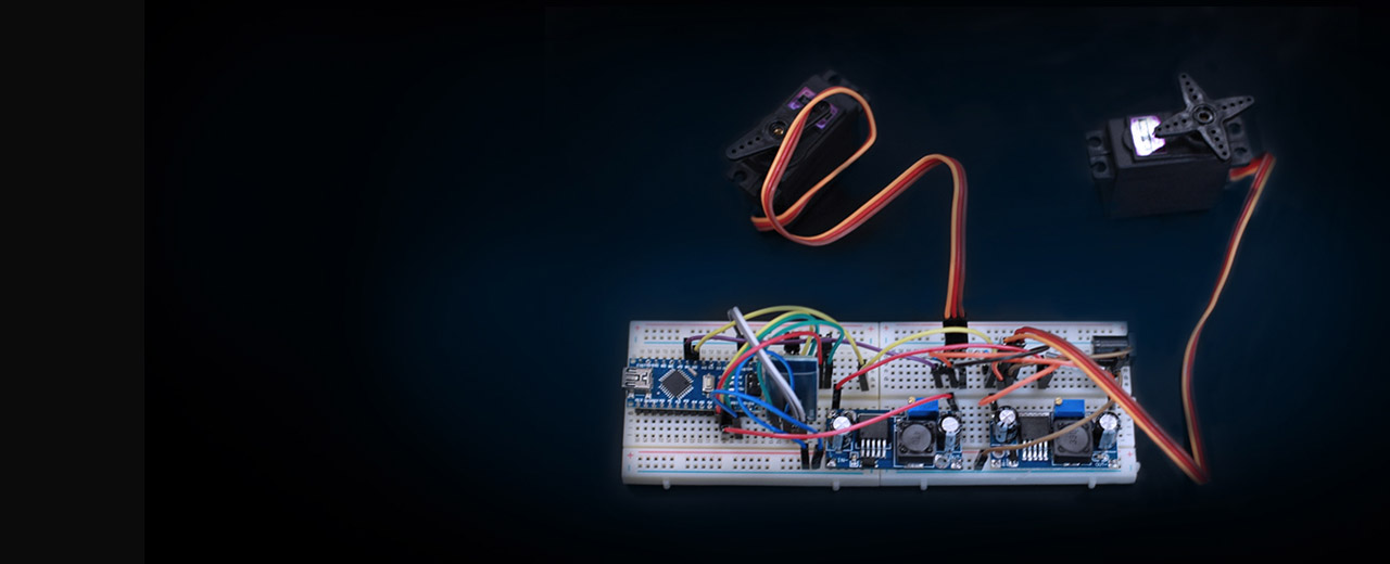
The SB 4.0 board uses an Arduino Nano 3.0 platform with an ATmega328 8-bit microcontroller. This is enough for the code processing and solution of many tasks, such as: robots and a “smart home” system control and a lot more.
The SB 4.0 board’s logical voltage is 5 V. It provides the electrical compatibility with the Arduino periphery.
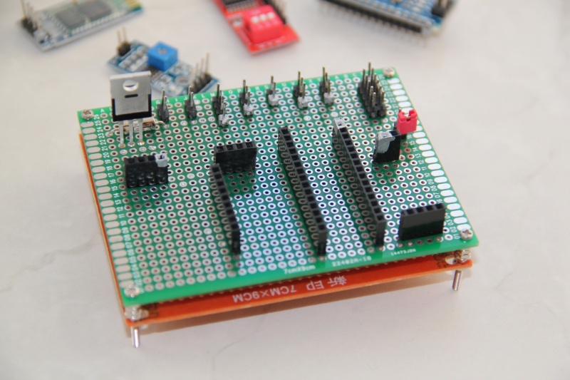
The following control pins are available:
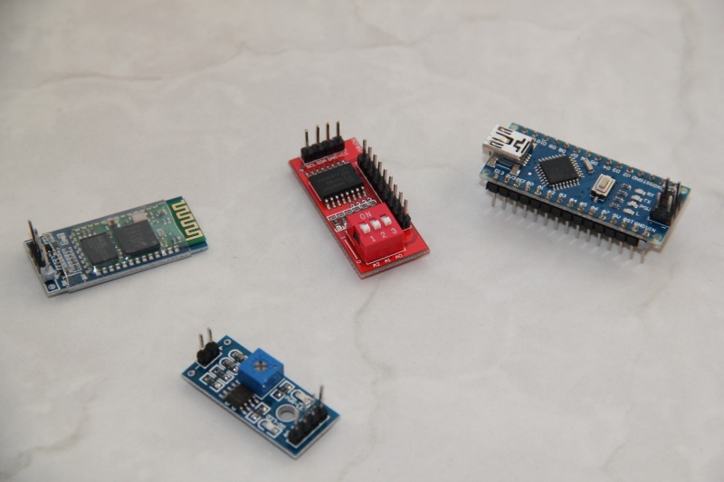
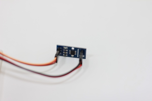
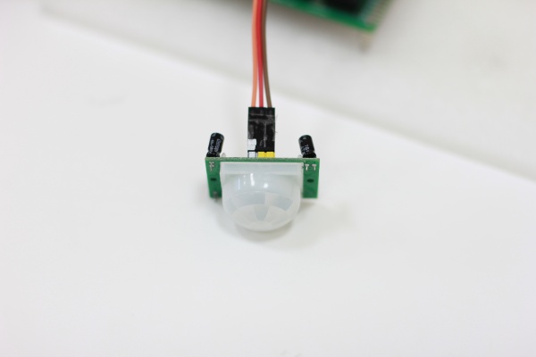
On the Arduino Nano platform the following ports are available: I2C, UART, analog IO, which we use for the port expander board, the Bluetooth module, and the light sensor.
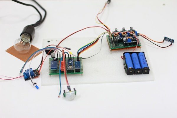
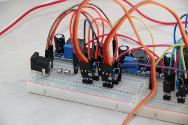
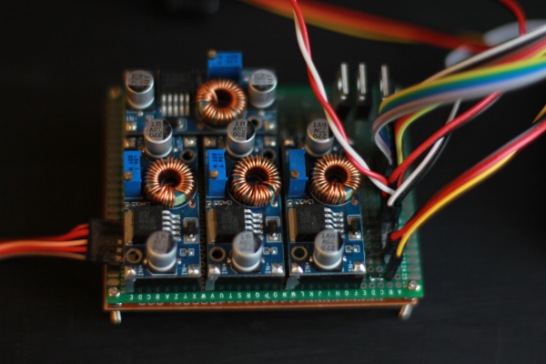
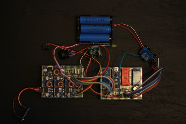
It is possible to use an AC adapter or Li-Ion batteries with a charge controller as a power source. The power source is determined automatically.
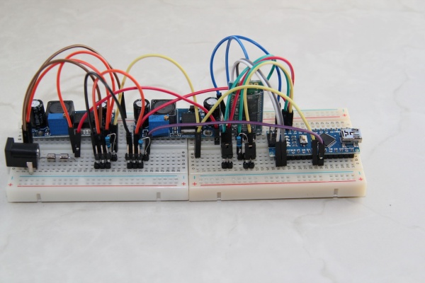
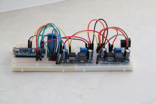
The recommended input voltage in case of the external power supply is 12-12.5 V. The DC-DC voltage converters step down the voltage going to the servos to 7 V and step down the voltage going to the USB1, USB2 and the rest of the loads to 5 V.
Use the 5V pins to power the periphery. When using an external power supply, it is possible to receive from a 5V pin up to 1A in total.
The recommended power supply set includes:
The Arduino Nano microcontroller (MC) is programmed via the USB with the standard free software from the MC manufacturer’s site. To transfer the data between the SB 4.0 and a computer we use an inexpensive common Bluetooth module HC-06; the data transfer rate is 9600 KB/sec. The telemetry data and control commands go via this wireless channel. All this is managed with the help of the software interface, SelfieBot Control Panel, written with the help of the LabView.
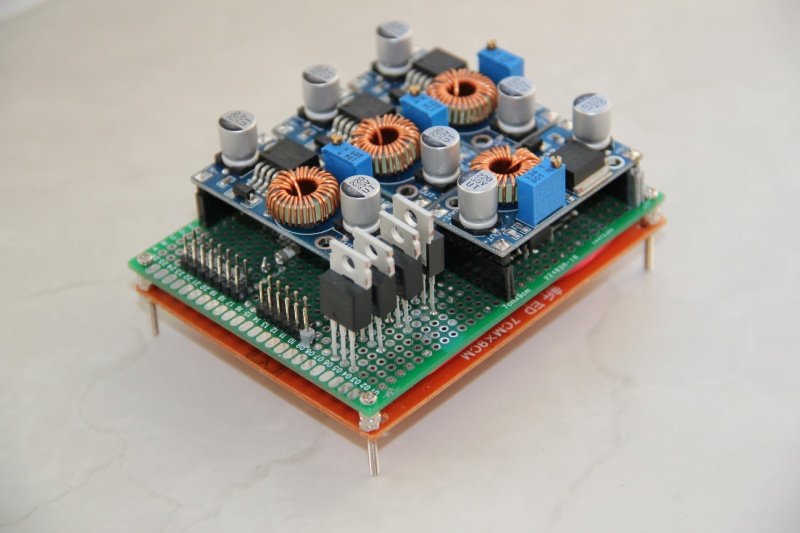
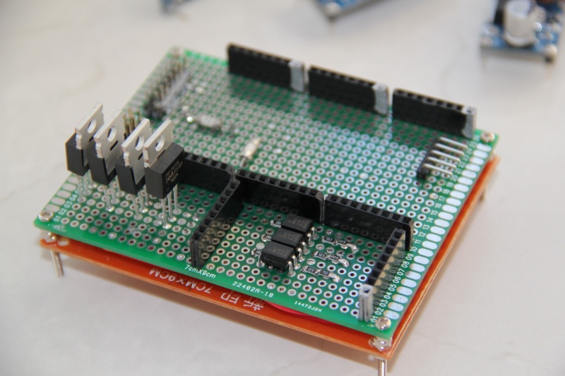
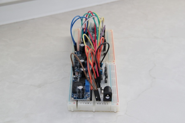
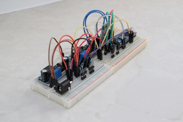
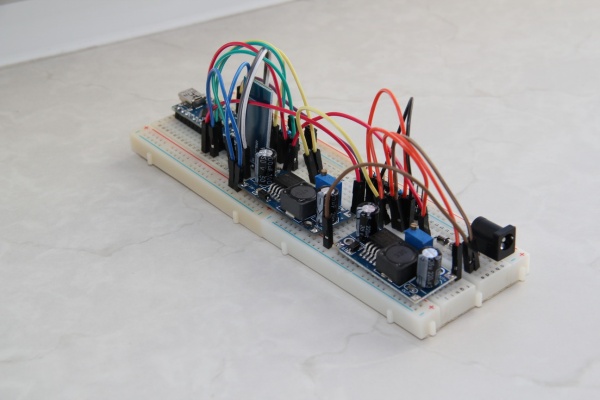
The board size is 90 × 70 × 40 mm. The external power supply and USB sockets protrude beyond the mentioned sizes a little bit. The board has fasteners at its corners. The contacts are spaced apart at 0.1" (2.54 mm).
The control board includes the following elements:
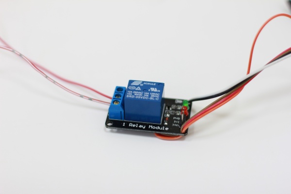
The board is able to control not more than two servos (e.g. TowerPro MG996R); it is able to report the electronics state via an RGB LED and power, for example, a relay module with the 5 V supply.
The SB 4.0 board is able to process both analog and digital input data:
The board task is sensors scanning, its data processing, sending the results on the software command, running the commands received from the software.
The preset:
The input pin (connected to the microcontroller pin) operation is based on the open/closed principle. The button connected to the input pin forms +5V or 0V on the MC. These values are digitized, processed, and displayed in the telemetry, which is sent to the software.
The output pin is either disabled (0V) or gives 5V with a load capacity of 1A. Voltage to this connector is applied on an external command or on a firmware algorithm command.

 Save 148$ today!